Ok - here are the last photos of construction. I am having to blog these four at a time because I am using Picasa's "blog this" feature - for some reason the web interface is down on blogger and I can't sign in that way.
I was lucky to have the network jack fit so nicely. I had to cut the metal "frame" that used to clamp the cord (see previous post photos) in order to fit the jack, but after that and careful cutting out of the pen marked area the jack fit nicely and its inbuilt clips hold it in place when the cover is closed - no glue involved, though I had it ready :)
Other installation notes: I used a small jeweller's saw to make the cuts, but a coping saw or fretsaw or even a saw blade attachment on a dremel would work. Also notice in a previous post how I re-wound the wires (flash shoe end) around the little metal "choke" before punching them down on the network jack - this is important because it stops any spikes of HV electricity from travelling the wires.
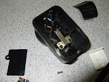
You can see the wiring inside the camera module. I used a piece of network cord for the wires since the jack is made for that kind of wire anyway. I did use a "real" punchdown tool but you can buy a package of these jacks that has a little plastic punchdown tool in with them. I have also used a small screwdriver in the past but it is hard to do properly.
I tested the setup with a multimeter the first time - I plugged in a network cord and tested for continuity between the pins of the camera module to the flash shoe and also to see if there were shorts between any pins... had a bit of a heart palpitation as the blue wire (trigger) had no continuity... I checked my connections and found nothing wrong, then disassembled the flash shoe end to find a small component inline (see pic). I thought perhaps a diode to stop backfeed? At any rate then I felt secure enough to test on camera. Results follow in the next post...

The inside of the camera module finished

The inline component

The finished setup


